Proper Interpretation of ABC Positive Sequence
Abstract – Power systems operating according to a specified sequence or rotation, is one of the most important and integral components of a multi-phase power distribution network. Without proper sequence, the design and integrity of the 3-phase power grid becomes compromised. Some of the prime effects of not having proper sequence include:
- Synchronization between sources is not possible
- Loads malfunction and motors rotate in the wrong direction, leading to damage
- Load balance becomes violated
By definition, phase sequence outlines the order in which each phase-to-neutral voltage waveform reaches its maximum instantaneous magnitude. This order, or sequence, is completely predicated on the phase angle associated with each discrete voltage waveform which comprise the 3-phase power system. Therefore, to determine sequence, we need to closely analyze the phase angle associated with each of the aforementioned waveforms, in both the time and frequency domain.
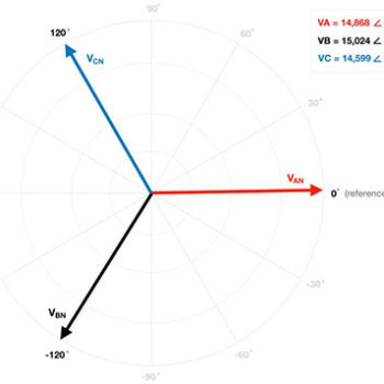
Frequency Domain Analysis – Leveraging Euler’s formula, we can quickly and conveniently transfer an AC waveform from the time domain to the frequency domain – most devices such as meters and relays display voltages (and currents) as phasors in the frequency domain. Note, a phasor is simply a complex number (vector) that carries the amplitude (in its magnitude) and phase angle (in its direction) of a periodic AC waveform. If the power system is being driven by a balanced 3-phase source, all voltage phasors should be equal in magnitude and 120° directionally displaced. Below, is an example of the phasor diagram extracted from an SEL-487E relay with actual recorded magnitudes and phase angles.
If we accept this assertion as true, than the new direction associated with each voltage phasor is:
- PHASE A: +2.05°
- PHASE B: -122.79°
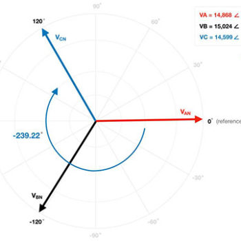
- PHASE C: -239.22°
By analyzing the above angles, we should note the negative sign associated with PHASE B (-122.79°) indicates that it lags PHASE A by ~120° and the newly derived negative sign associated with PHASE C (-239.22°) indicates that it lags PHASE B by ~120°. Since the word “lag” entails a delay in time, we can now make the claim: PHASE B is delayed with respect to PHASE A and PHASE C is delayed with respect to PHASE B. The sequence (rotation) of the voltage phasors should now be evident, given their respective time delays: ABC. Let’s now transition to the time domain and prove the ABC positive sequence rotation given the SEL-487E registered voltage phase angles.
Time Domain Analysis – If we plot the SEL-487E registered magnitude and phase angle values in the time domain and using the convention of red for PHASE A, black for PHASE B, and blue for PHASE C, yields the below illustration.
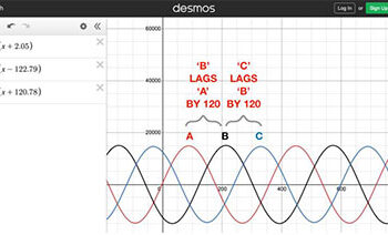
Note the SEL-487E phase angles (left hand corner) and the sequence (rotation) of the corresponding waveforms as time elapses, from left to right: ABC. Again, to make the rotation more intuitive, we will change the angle associated with PHASE C from +120.78° to -239.22° and re-plot the waveforms.
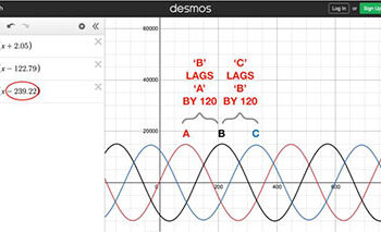
Notice, there is no change in the affected waveforms or their ABC sequence (rotation) when PHASE C is changed from +120.78° to -239.22°. This means that an advance in time of 120.78° (+120.78°) is identical to a delay in time of 239.22° (-239.22°). Since we are now in the time domain, it is good practice to convert the lag between the discrete waveforms from degrees to their corresponding value in seconds. To execute the conversion, we simply divide the angular displacement (lag) – expressed in radians – by the system’s angular frequency 𝜔=2𝜋𝑓.
Per the diagram, the voltage supply satisfies both the magnitude and phase angle requirement of balance. Next, we need to determine the sequence – also referred to as the rotation – of the voltage supply. As previously mentioned, the rotation is dependent on the phase angle (direction) associated with each voltage phasor. According to the SEL-487E relay, the reference phase (PHASE A) has a direction of +2.05°. PHASE B has a direction of -122.79° while PHASE C is operating at +120.78°. Note, positive phase angles are measured in the counter-clockwise (CCW) direction from the 0° reference axis, while negative phase angles are measured clockwise (CW) from the 0° axis.
- Aliquam tincidunt mauris eu risus.
- Vestibulum auctor dapibus neque.
- Nunc dignissim risus id metus.
- Cras ornare tristique elit.
- Vivamus vestibulum nulla nec ante.
- Praesent placerat risus quis eros.
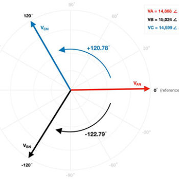
In an effort to simplify the phasor diagram, I postulate that replacing the +120.78° angle of PHASE C with an angle of
-239.22° has zero impact on the system.
For a 60Hz power system, a lag of 120° translates to a delay in the time domain of,
2𝜋3⁄2𝜋𝑓= 2𝜋3⁄2𝜋(60)=1180=0.0055=5.5ms
Therefore, PHASE B lags PHASE A by ~5.5ms and PHASE C lags PHASE B by ~5.5ms – validating the ABC rotation of the power system as registered on the SEL-487E relay.
Concluding Remarks – Whenever PHASE A is considered the reference phase (0°) and PHASE B has an angle of -120° while PHASE C operates +120°, the system must be positive sequence ABC rotation as outlined in this paper, regardless of measuring device or relay used to extract the information. Moreover, we can replace the angle on PHASE C, from +120° to -240°, without impacting the system – this convenient change allows us to quickly identify that PHASE C (-240°) lags PHASE B (-120°), thus we must conclude ABC rotation.

